The scene tab  will display information about the current road network. You can choose the preferred handle to move markers and after selecting a road or crossing object the Inspector will display information about that object. will display information about the current road network. You can choose the preferred handle to move markers and after selecting a road or crossing object the Inspector will display information about that object.
After adding a road or selecting a marker (blue sphere handle) of an existsting road the road properties are displayed:
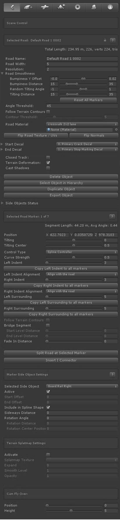
Locked Objects
At the top right next to the road name you see a lock. You can use this to lock all the road settings. Togther with the "Exclude Locked Objects" option in Scene Settings, this can also be used to hide the road handles in Scene View.
Road Object Properties
- Road Name: The name of the road
- Road Width: The width of the road
- Sub Segments [Pro]: This can be used to subdivide the road mesh for more detail. Note that this is not supported yet on dynamic crossings.
- Resolution: the geometry resolution in meters
- Angle Threshold [Pro]: This can be used to optimize the road geometry while still maintaining detail in bends. Try values around 5 and increase the road resolution to 10 or 20. The vertex / triangle count will drop significantly. In general it is not recommended to use a lower Angle Threshold than 4 or 5 unless you are after high definition.
- Road Smoothness [Pro]:
Bumpiness Y Offset: The smoothness level of the road controllable through Min Max values
Bumpiness Distance: The distance controlable through Min Max values
Random Tilting Angles: Adds additional tilting to the road controllable through Min Max values
Tilting Distance: The distance over which the tilting takes place.
- Follow terrain Contours [Pro]: The road will auto adjust to the terrain shape, this will greatly speed up the workflow as less markers will be required
- Contour Treshold [Pro]: The accuracy. Use lower values to exactly match the terrain shape, use higher values for roads like motorways.
- Road Material: the material assigned to this road. The dropdown lists all materials in /EasyRoads3D/Resources/Materials/Roads and can be used to quickly assign another material. It is recommend though to work with road types and apply the material changes to the road type.
- UV Tiling: This controls the tile size of the used road texture.
- Additional UV data: Additionally uv data matching the terrain boundingbox or uv data tiled on a specified distance can be generated in UV channel 4.
- Flip Road Texture / UVs: This will swap the uv coordinates of the road. By default texturing of opposite roads on a connection will match regardless how they are connected to the crossing. If you do not want that for specific roads, you can change that by flipping the road texture of a road. This option can also be useful for roads connected to custom connectors when the UVs look wrong or flipped.
- Flip Normals: This can be useful for tracks generated through the custom prefab system. Soemtimes you want thw normals to point to the other direction like for tunnel / cave type of shapes.
- Start Decal: The currently selected Decal at the start, this can be updated manually by selecting another deval from the dropdown. Decals can be used as a transition between road types at crossings or to add variation, cracks, road fixes. Decal prefabs can be added per road type in General Settings > Road Types.
- End Decal: The currently selected Decal at the start, this can be updated manually by selecting another deval from the dropdown. Decals can be used as a transition between road types at crossings or to add variation, cracks, road fixes. Decal prefabs can be added per road type in General Settings > Road Types.
- Closed Track: This will loop the road, ideal for generating race tracks
- Terrain Deformation: This can be used to turn off terrain deformation for this particular road, for instance roads used as bridge segments.
- Cast Shadows: Toggle this on when the object should cast shadows.
- Delete Object: this will remove the object
- Select Object in Hierarchy: This will select the actual road object. It doesn't really serve a purpose other then providing a quick way to actually select that road in the hierachy
- Duplicate Object: This will copy the object which is useful if you need a range of similarly shaped objects.
- Export Object: This will export the selected road to .obj
Side Objects Status
This will list all available side objects in the scene. You can select which side objects to activate for this road object.
The foldout will show additional controls to adjust the default settings of this particular instance of the side object.
The X Position relative to the default position with options for randomness. The same for the Y position and random rotation angles.
Marker Properties
- Position: The XYZ position of the selected marker
- Tilting [Pro]: The tilting angle of the selected marker (use the E key to control this directly in scene view). For objects with terrain deformation the rotation angle is locked to max 30 degrees. Other objects can rotate on the full 360 degrees which can be useful for FX type tracks.
- Tilting Center [Pro]: The origin of the rotation.
- Control Type [Pro]: Per marker you can select the Control Type. Spline Controller is the default Controller and will create smooth curves. Straight XZ will connect this marker with the next marker on a straight line but with a smooth height transition. Straight XYZ will connect this marker with the next marker on a perfact straight line. Circular will create a circular shape between the selected marker and the next marker based on the angle with the previous marker.
- Curve Strength: This will be available when using the Spline Controller as the Control Type and will control the strength of the spline shape.
- Left Indent: The distance on the left side of the road over which the terrain should be flattened at the same height.
- Left Indent Alignment: This can be used to manipulate terrain deformation in hilly areas. Align with Road is the default option and generally you want to use this setting. The two other options are useful in hilly areas where you want to add more definition to the terrain near the road by faking terrain through meshes which can be done through the side objects system, specifically the Shape Object type. Align with the terrain will snap the indent values to the terrain height at that point. Align with surrounding position will set the indent position at the same height as the corresponding left surrounding position.
- Left Surrounding: The distance over which the terrain should gradually be flattened to the original terrain height.
- Right Indent: The distance on the right side of the road over which the terrain should be flattened at the same height.
- Right Indent Alignment: This can be used to manipulate terrain deformation in hilly areas. Align with Road is the default option and generally you want to use this setting. The two other options are useful in hilly areas where you want to add more definition to the terrain near the road by faking terrain through meshes which can be done through the side objects system, specifically the Shape Object type. Align with the terrain will snap the indent values to the terrain height at that point. Align with surrounding position will set the indent position at the same height as the corresponding right surrounding position.
- Right Surrounding: The distance over which the terrain should gradually be flattened to the original terrain height.
- Follow Terrain Contours [Pro]: This options is enabled when the main Follow Terrain Contours checkbox in the road properties is checked. You can use this to turn off this feature for specific individual markers and, for example, create raised bends in hilly areas.
- No Terrain Deformation: This will deactivate terrain deformation for this marker segment which is required for example for bridge segments.
- Start Level Distance: The distance over which the terrain height will be leveled from the road height to the original terrain height at the start of the bridge segment.
- End Level Distance: The distance over which the terrain height will be leveled from the road height to the original terrain height at the end of the bridge segment.
- Fade In Distance [Pro]: This option will be displayed when the first marker is selected. You can use this to fade the road in over x meters. Note that the EasyRoads3D transparent shader is required for this. Or you can modify your own custom shader accordingly.
- Fade Out Distance [Pro]: This option will be displayed when the last marker is selected. You can use this to fade the road out over x meters. Note that the EasyRoads3D transparent shader is required for this. Or you can modify your own custom shader accordingly.
- Custom Vertex Color: this info can be used in custom shaders.
- Split Road at Selected Marker: This will cut the road and create a new road object at the selected marker
- Insert I Connector [Pro]: This can be used to connect non matching road types, blend road types (like asphalt / dirt roads) or change the road material on a segment. More Info
Additional marker options. The R key will remove all selected markers. The "I" key will insert a marker at the mouse position in the scene. More Shortcuts, Hotkeys
Marker Side Object Settings
- Selected Side Object: The below options will affect the currently selected side object int the dropdown
- Active: The active state for this side object for this marker
- Start Offset: The position relative to the marker where the side object should start. This option will be enabled when the previous marker is not active. This is useful for, for example, aligning bridges with the terrain. You can also set this value using the slider in scene view.
- End Offset: The position relative to the next marker where the side object should end. This option will be enabled when the next marker is not active. You can also set this value using the slider in scene view which will be visible when the previous marker is not active.
Tip: Use for example the R Key to toggle off the marker position handle when this is interfering with the slider handle.
- Include in Spline Shape: this is for side objects build along their own spline shape relative to the main track using Sideways Distance Settings. By disabling markers you can control the shape of the side object better in for example sharp corners.
- Sideways Distance: The Sideways Distance for this marker relative to the center of the track.
- Rotation Angle: Per marker you can apply manual rotations to the side object. This can be useful for side objects like fences or guard rails.
- Rotation Distance: The distance over which the rotation will be applied.
- Rotation Center Position: The offset relative to the selected marker for the center of the rotation.
Add Shape to Terrain Splatmap [Pro]:
For every road in the scene you can selected whether the road shape should be embedded in the terrain splatmap. It is a useful feature to blend the road with the terrain.
- Activate: This will activate splatmap blending for this road
- Splatmap Texture: This will list all the availabe terrain splat map textures. Select which texture you want to use.
- Expand: This will increase the size of the road shape. The value is an Int value representing the number of splatmap indexes.
- Smooth Level: This will gradually blend the selected texture with the original terrain splatmap. The value is an Int value representing the number of splatmap indexes.
- Opacity: Use this to set the blend strength of the road shape with the original terrain splatmap. This is a float value in the 0..1 range.
Cam Fly Over
The Cam Fly Over feature is useful to quickly explore the selected road.
- Position: The Position slider will move the scene cam over the road.
- Height: This will set the scene cam height above the road
Crossings can be attached directly to a road by selecting the first or last marker of that road. In the Inspector you will see all available crossing / connection objects. Click the object you want to attach to the selected marker.
Alternatively you can add crossing objects directly to the scene, especially roundabout objects, by clicking the connection prefab tab  . You will see the same list of available crossing / connection prefabs. Select the object you want to instantiate in the scene, hold the SHIFT key and click in the scene where you want to position the object. You can repeat SHIFT + click if you want to instantiate the same object multiple times. . You will see the same list of available crossing / connection prefabs. Select the object you want to instantiate in the scene, hold the SHIFT key and click in the scene where you want to position the object. You can repeat SHIFT + click if you want to instantiate the same object multiple times.

After Instantiating a connection in the scene or selecting an existing connection in the scene the Inspector will display connection properties and controls
- Position: The position of the connection
- Rotation: The rotation of the connection
- Rotate Connection: Depending on the connected roads, this button will rotate the prefab and swap connections
- T-Crossing: This is active on dynamic X, T crossings and will build the prefab according this status
- Sidewalks: This is active on dynamic connection prefabs and will set the global sidewalk status
- Delete Connection: This will remove the connection from the scene
- Select Connection in Hierarchy: This will select the actual rotation game object. For dynamic crossings the connection properties will be displayed.
The I Connector differs from other Connection prefabs in a way that it not a prefab physically available in the assets folder or in the Connection Prefabs tab, the 3rd tab from the left in the Inspector.
I Connectors are directly attached to any marker. If this is not the first or last marker of the selected road, the road will be split in two roads at the selected marker with the I Connector in between the two.
I Connectors can be used for:
1) Blending roads, for example asphalt roads and dirt tracks.
2) Using different materials on a specific road segment
3) Connecting non matching road types
4) Cut roads in pieces for occlusion culling or streaming sections.
I Connector Properties
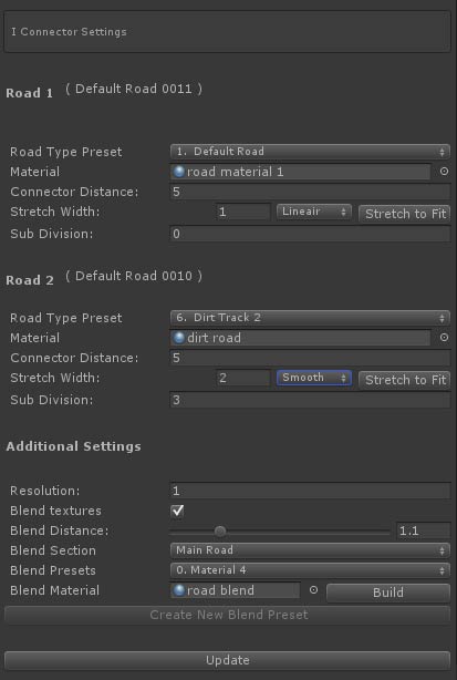
- Road Type Preset: The road type of the connected road. If no road is connected, new roads pulled out of that connection will be of the selected road type.
- Material: The material assigned to the road. This currently has no function.
- Connector Distance: By default the IConnector will connect both roads. Setting a Connector Distance will make it possible to adapt road widths and / or blend different road types.
- Stretch Width: This will adapt the width over the connection distance. Options are Lineair, exponentional and smooth. "Strech to fit" will auto auto set the stretch level to match width of the other road.
- Sub Division: Stretching can result in zigzag type of texturing. The Sub Division level will be useful here. The higher the value the more the zig zag effect will be reduced.
- Resolution: The geometry resolution of the Connection
- Blend Textures: This will activate the blend options
- Blend Distance: The distance over which the textures will blend
- Blend Section: The blending can be done over the main connection (road 1), road 2 or over both sections. In general you want to use the wider road. For example a wider asphalt road with dirt track blending on the asphalt section.
- Blend Presets: This is not active yet. It is intended to auto assign I Connector settings based on the involved road types.
- Blend Material: The material used for the blending. Examples are the shaders "ER Dual Road Blend" for two different road types and "ER Single Road Blend" for the same road types. The "Build" button will auto set the material based on the materials on the connected road objects provided that these shaders have standard Unity property names are (_MainTex, _BumpMap, _Metallic, _Glossiness, _Color, etc.);
|