|
EasyRoads3D V3 Manual | |
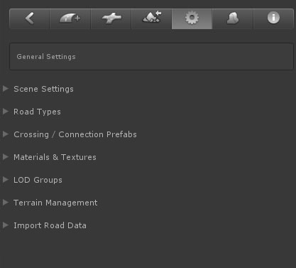
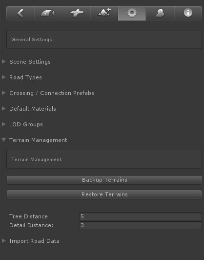
General Settings The General Settings tab
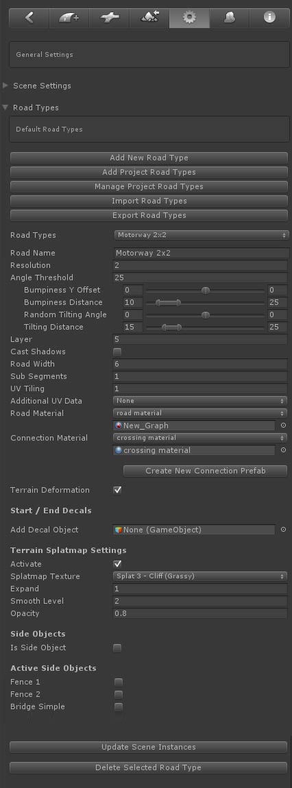
Especially when building complex road networks with different road types it is recommended to setup road presets before actually building your roads in the scene. These presets will be available when adding a new road to the scene or when setting up crossing / connection objects and is an easy way to make sure road types look the same and match with the associated crossing types. You can also link road presets to OSM road types. Most of the properties refer to the same properties as for road objects in the scene. The other controls are explained below.
CROSSING / CONNECTION PREFABS [Pro]
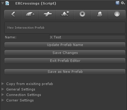
EasyRoads3D supports two systems to create crossings, often referred to as "connection prefabs" because these type of objects do not necessarily have to be crossings, but can also, for example, be mesh based crosswalk prefabs. The main system is the dynamic prefabs system, these are built-in customizable connection prefabs. The second, very powerful system, is the custom mesh prefab system with which you can turn your own models into connection prefabs. You can use this to further customize your road networks whilst still taking advantage of the EasyRoads3D scene workflow. With the dynamic crossing system you can currently build standard X , T crossings and roundabout prefabs. This is especially useful when you have many similar types of crossings in the scene. By creating a prefab first you can reuse this prefab in the scene without having to customize it each time. You will still be able to create variations of an instance of this prefab in the scene. /Assets/EasyRoads3D/Resources/dynamic prefabs 1) enter a name for the new crossing prefab in the "New Prefab Name" textfield. 2) select from the dropdown what type of crossing preset you want to create, crossing or roundabout. You can also create a new prefab from an already existing prefab by selecting this existing prefab from the Create Copy of dropdown. This is useful to quickly create prefabs with variations. 3) Click the Create resp. Create New Prefab (in case you create a copy of an existing prefab) button. This will create the new prefab in the above mentioned folder 4) Hold the SHIFT key and click in the scene. The newly created prefab will be instantiated in the scene as a child of Temp Crossing prefabs because we are only temporarily instantiating it in the scene to customize it. 5) Use the Inspector and scene controls to customize the new crossing prefab, see just below 6) Make sure to click the Save Changes button to update the prefab. But only do this for new prefabs, NOT for instances already used in the scene! NOTE: The above is not yet fully implemented for roundabouts. Instead drag drop the newly created prefab from the project folder in the scene, build the roundabout and use the standard Unity way to update prefabs: Main Menu > GameObject > Apply Changes To Prefab
After instantiating new crossing prefabs in the scene you will see the following Inspector: Name / Update Prefab Name: You can use this to change the prefab name
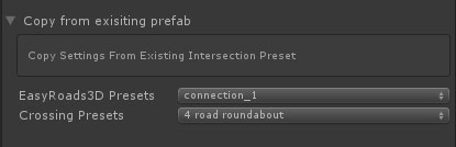
Use this if you want to create a new prefab based on one of the prefabs that come with EasyRoads3D or based on a crossing prefab you already created before
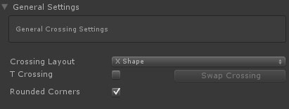
Crossing Layout: This controls the geometry structure and style of the crossing. At this moment only X Shape is implemented. Other options will follow.
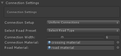
Connection settings refer to the road characteristics at each side of the crossing / connection which can all have their own specific characteristics. Connection Setup: This dropdown includes three options. Uniform Connections, the selected road settings will be applied to all four connections. Uniform Opposite Connections, the front and back connections share the same settings and the left and right connections share the same settings. Unique Connection, each connection will have its own specific settings. Select Road Preset: This is where road presets come in useful. Simply select one of the available road presets to set the connection info. Also with regard to future features it is strongley recommended to use this workflow instead of manually adjusting individually settings such as the width here below. Of course you can still do this for a specific road in the scene that will not be reused elsewhere. Creating a new road type only for a single road is not necessary and wouldn't be efficient. Connection Width: this will be the width of the connection. It will be inherited from the selected road type but could be customized for a single crossing in the scene that will look different. Connection Material: the material used on this crossing connection geometry Road Material: The material that will be assigned to roads attached to this connection
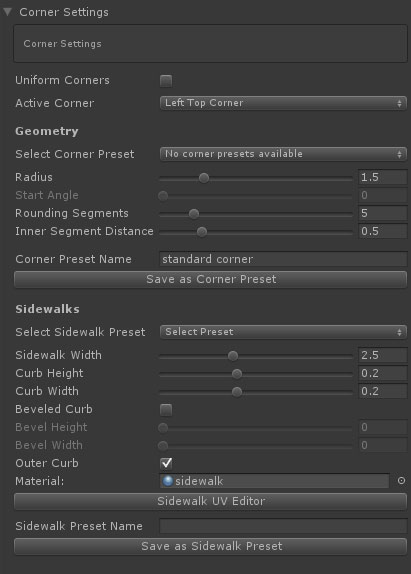
[add scene view image visualizing the above properties] Each corner of a crossing can have its own properties both for the road corner shape as for sidewalks. Corner Settings Uniform Corners: when checked corner changes will be applied to all crossing corners. Select Corner preset: You can store corner settings further below in the Inspector. Currently saved settings will be displayed here. This can be used to quickly assign the same corner settings to other corners across all crossing / connection prefabs. Simply selected the wanted preset from the dropdown. Radius: The size of the rounded corner Start Angle: This option is enabled when the second road is snapped to the main road (like a dirt road to an asphalt road). This way you can create flexible non 90 degree roundings. Rounding Segments: Use this to get the desired geometry resolution for the rounding Inner Segment Distance: This controls the distance of the inner row road vertices and depends on the nature of your road texture, the thickness of markings or other design elements at the sides of the roads that need to be preserved. Corner Preset Name: As mentioned you can assign presets to a corner. Here you can enter the preset name if you want to store the current settings as a new preset Save as Corner Preset: Click this button to store the current corner settings as a new preset after entering a name
Select Sidewalk Preset: Just like with crossing corners, you can create presets from the current sidewalk settings. This can be used to quickly assign the same sidewalk settings to other sidewalks across all crossing / connection prefabs. Simply select the required preset from the dropdown. Sidewalk Width: The full width of the sidewalk Curb Height: The height of the sidewalk Curb Width: In order to accurately assign UVs in corner roundings additional vertices will be generated. The width of the curb depends on your sidewalk texture. You can manually adjust the UVs further below through the Sidewalk UV Editor explained further below Beveled Curb: This will generate more complex geometry for the sidewalk Bevel Height: The height of the additional segment. Keeping this at 0 will create a diagonally shaped sidewalk Bevel Width: The width of the added diagonal segment. Outer Curb: This will add a extra triangles at the outer side to the road level Material: The sidewalk material Sidewalk Preset Name: Here you can enter the preset name if you want to store the current sidewalk settings as a new sidewalk preset Save as Corner Preset: Click this button to store the current sidewalk settings as a new preset after entering a name Sidewalk UV Editor: EasyRoads3D will auto assign UVs based on the above settings. Optionally you can fine tune these UVs. The Sidewalk UV EDitor button will open a window that will display the texture assigned to the above selected material. Depending on the chosen complexity of the sidewalk geometry you will see handles at the bottom. Moving these handles will auto update the UVs in the scene. Click here for more info.
Connection Handles in the Scene: - Near each crossing corner 3 sphere handles are displayed. The middle handle controls sidewalk rendering for this corner in general. The outer two handles control whether sidewalks should be added to roads connected to these crossings. - You will also see grey handles in the center of each crossing. After clicking the grey handle it will display in white, the connection prefab will be aligned according the to this connection attached road direction. Inspector > UV Editor button The UV Texture window will appear with the selected road texture displayed on the canvas. This window can be used to correctly map the sidewalk UVs. Drag the green handles horizontally. You will see that the UVs update directly in the scene. It is recommended to start with the sidewalk on the left side of the connection (looking towards the center of the object). If the sidewalk on the right side matches you can afterwards click the mirror button, this will mirror the left hand UVs for the right side. If a handle appears to be undraggable, deselect and reselect it!
[to do: describe this process, the workflow is almost identical to customizing dynamic crossings] NOTE: It is recommended to set the Radius and Resolution first before adding connections. You can adjust both afterwads but it could be that connections cannot be created anymore because there is not enough space to fit the connections based on the current settings. This will be optimized further, for now focus on the handles displayed in the scene. These handles represent the selected connection position. Move all connections so the associated handles do not overlap. The roundabout will be rebuild as soon all connection positions do not overlap each other. Alternatively change the radius of connections or increase the radius and /or resolution.
Custom connection prefabs are mesh based prefabs prepared to be used within the EasyRoads3D system. These can be your own unique models created in a modelling app. The system supports prefabs with child objects and submeshes. Currently all prefab mesh data will be read in. http://youtu.be/yDUhBZg7tQM - customized road networks - Part 1 This is how it works: 1. Select the General Settings tab from the toolbar in the Inspector.
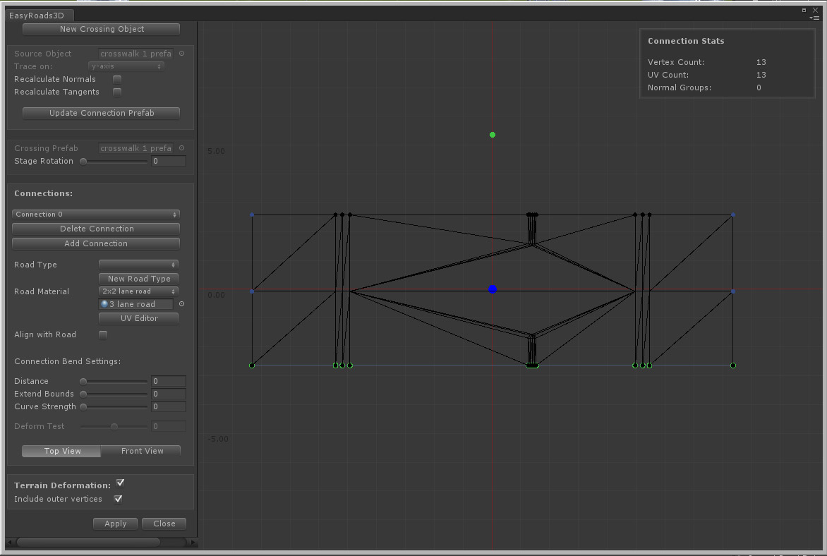
The new custom crossing prefab will now appear in the list of available custom crossing prefabs in the scene tab when the first or last marker is selected and in the prefabs tab where you can select the new custom prefab and directly instantiate it in the scene. NOTE: Add connections in clockwise direction preferably starting at the bottom. NOTE: You can edit already generated custom prefabs by opening the window and dragging the prefab from the the assets folder (/Assets/EasyRoads3d/Resources/custom prefabs/) directly on the stage or in the Crossing Prefab slot. NOTE: In order to be able to edit custom prefabs in a later stage, do not remove the original mesh object from the assets folder. NOTE: The terrain will be flattened according the local Y=0 position. Depending on the model type, make sure that all vertices are at Y = 0 or higher. NOTE: to avoid z-fighting / flickering make sure to use one of the EasyRoads3D shaders on the material assigned to the custom prefab. NOTE: Although this system should support relatively complex shapes (also none roads related), connections should always point outwards relative to the center of the object. Meaning, roads/tracks connected to this crossing should move away from the center at the connection point which usually is the case for road type of networks. So make sure the center of the mesh bounding box is at the pivot point, the larger blue dot in the image above. NOTE: The system supports, non "flat" connections for prefabs that do n ot connect with the terrain. This is useful to create for example bridge elements as part of the road geometry. Please check the example prefabs in the package on how to set this up. Important is that the UVs of the vertices where the geometry connects are accurate, 0 resp 1. A small inaccuracy of up to 0.01 will work but you do want to stay within this margin. If the connection does not extract well, this is the first thing to double check. Also make sure to not close the connection area with triangles that will not be visible anyway after connecting roads. NOTE: This custom crossing prefabs system has been tested with a fair amount of different meshes. But models can have any arbitrary shape. If you experience issues with your own models please report this ideally including the source mesh at info@unityterraintools.com
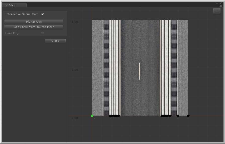
The UV Editor window can be used to make changes to the UV layout for dynamic crossing sidewalks and road connections added to custom crossing prefabs. By default UVs are calculated within the 0..1 range based on the distances between these vertices. The textures assigned to the used material for these objects is displayed on the canvas. At the bottom you will see the UVs positions per vertex. If this is not accurate, You can move these points to the matching position on the texture.
Note: When the UV Editor window is opened from the Custom Crossing editor, selecting a point will highlight the corresponding vertex in the Custom Crossing editor window. This way you can see for which vertex you are adjusting the UVs. Note: When using Copy UVs from source Mesh and the connection has a closed geometry structure (the first and last vertex positions are the same), usually these vertices use x = 0 and x = 1 as the UV coordinate. It could be that these values are assigned to the wrong vertex and need to be swapped. You will clearly see this in the scene after attaching a road, the full texture is visible between two vertices. Swapping the UVs is done by dragging the most left (0) to the most right position (1) and the most right to the most left. [Add this to trouble shooting as well]
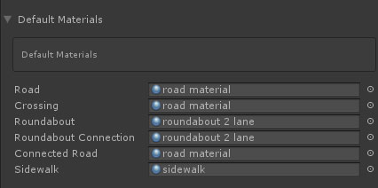
Here you can set the default material which will be auto applied when creating new roads, crossing or roundabout prefabs. [WIP] This section also includes options to set texture info. For now you can define lane marking info. This info will be used in new crossing features available in v3.x but it can also be used to automatically generate base textures for roads with different width to make that sure outer lanes connect nicely on crossings between these roads with different widths.
The LOD Groups option will create different LOD levels of the road meshes according the above settings.
NOTE: In order to actually create the LOD groups Build LOD Groups in the Build Settings must be active.
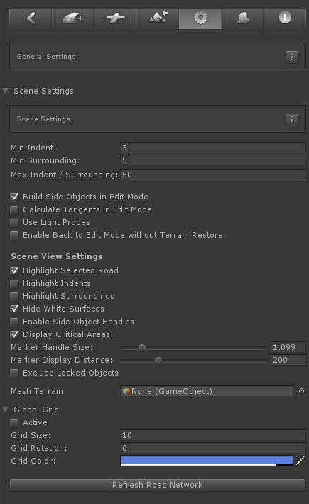
EasyRoads3D will alter the Unity terrain object(s) in the scene. Here you can create backups and restore your original terrains. Whenever a new terrain object is detected in the scene you will be asked to create a backup. It is recommended to do so. It is also recommended to update these backups after manual changes to the terrain to keep these backups up-to-date. The backup / restore options are also displayed in the Inspector of each individual terrain object in the scene. Alternatively you can also for example create backups of your terrain by duplicating the corresponding terrain asset in the project folder. Simply drag this terrain asset in the scene to replace the corresponding terrain you want to restore. Tree Distance and Detaild Distance refer to the surface outside the road where trees and detail objects should be removed. This is the default distance, in the final version this value will be tweakable per marker (to do!).
Vegetation Studio EasyRoads3D supports Vegetation Studio. If Vegetation Studio is present, an activation checkbox and additional perimeter options will be displayed here. Road type specific perimeters can be set for that road type in General Settings > Scene Settings
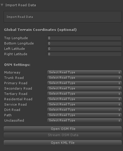
Road data from external sources can be imported directly into EasyRoads3D v3. The roads will be created automatically.
By default EasyRoads3D will match the bounds in the data file with the bounds of the terrain. However, if the coordinates do not exactly match those of the terrain, the terrain bounds can be entered in the corresponding terrain longitude / latitude fields. The data will be parsed relative to these terrain coordinates.
WORKFLOW Open Street Map Visit openstreetmap.org , zoom in to the location of your choice. Click the green "Export" item at the top. You will see lon lat coordinates and additional info at the left. Click the blue "Export" button. This will generate an *.osm file. For OSM data EasyRoads3D road types can be linked to OSM road type. For each OSM road type select the EasyRoads3D road type from the dropdown. Click the Open OSM File button in the Inspector and select the downloaded file. The system will extract the data and create the roads. Notes: The Stream OSM Data option is not yet functional. Also, currently this is implemented for a single terrain object. The next update will support multiple terrains.
|
|