Gear Indicator: A simple OutGauge client for "Live for Speed"
Author: Vladimír Kadlec
Email: vladimirkadlec ( a t ) gmail (d o t) com
Homepage: http://nlp.fi.muni.cz/~xkadlec
Index
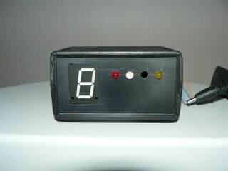
The Gear Indicator (GI) is a simple program, that allows the game to display
gear numbers on one 7 segment display connected to a LPT port. Additionally
several other information (such as "low fuel", "rpm limiter", etc.)
can be displayed. Supported games are Live for Speed and partially Richard
Burns Rally (RBR, see below). No support for rFactor.
I'm sorry, I don't own rFactor licence (and I'm not going to buy one).
NEW: Support for Richard Burns Rally. See GI Dll page for details.
GI expects, that LFS is configured to report "Dashboard Packets".
Change the following in cfg.txt file (it is in the LFS directory).
OutGauge Mode 1        :0-off 1-driving 2-driving+replay
OutGauge Delay 10      :minimum delay between packets (100ths of a sec)
OutGauge IP 127.0.0.1  :IP address to send the UDP packet
OutGauge Port 11111    :IP port
(the full description is in <LFS dir>/doc/InSim.txt)
Run GI.exe before LFS on the computer with OutSim IP.
127.0.0.1 is the computer, that is running LFS.
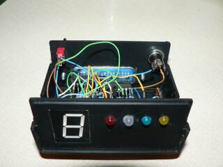
GI displays the gear on a 7 segment display connected directly
to data pins on the LPT port. Look at:
http://www.epanorama.net/circuits/parallel_output.html
and the section "Simple LED driving circuits".
Read the warning at the top of the page!
NEW: Circuit diagram and parts list by Nick_A,
thanks Nick.
For the shift indicator diode use the remaining data pin on the LPT.
For other information (rpm limiter, fuel warning, etc..) use
pins 1, 14, 16, 17. So the usual configuration is:
LPT port:
- pins 2-8 (7 pins): 7 segment display,
- pin 9: the shift indicator diode,
- pins 1, 14, 16, 17: other info diodes, the functions can be configured.
I really recommend to use two ULN2083 to protect your LPT. You don't need
the zenner diodes to the pin 10 on ULN2083, connect pin 10 to the +5V
directly.
The configuration for GI.exe is stored in "config.txt" in the same
directory as GI.exe. "Seg_N" section contains 10 numbers.
The number represents a value, that is send to the LPT port (data pins),
when a particular gear is reported by LFS. Change numbers to match
your wiring. It is usually easier to change the software configuration
than to change the hardware :-).
Because 7 segment display uses only 7 data pins, the remaining data
pin is used to display "shift light". Identify this pin in "Seg_Dot"
section in the config file. The number in the config file is equal
to 2 power number of pin. E.g. my shift light diode is on the 3rd
pin (counting from 0), 2^3 = 8, thus for me:
Seg_Dot 8
When rpm limiter is on, the gear shift indicator diode blinks,
notice the Blink_time option in the config file.
The functions for LPT pins 1, 14, 16, 17 can be also configured, see
"config.txt" for explanation. Possible functions are:
low_fuel, shift_light, traction_control, signal_lights, handbrake,
rpm_limiter, redline.
If you run GI with option "--blank-and-exit", i.e.:
GI.exe --blank-and-exit
then your display is blanked. The value of Seg_Off option and Ext_pins_off
option is send to the LPT port and GI exits immediately.
Q: Can I use this program do display only the shift light
(or a fuel warning, a rpm limiter...)?
A: Yes, just don't connect 7 segment. Only one diode is required :-).
Q: How do I discover the display codes for my 7 segment display?
A: Every segment on the display is represented by exactly one bit. First
of all, discover a bit on LPT port that lights particular segment on the
display. For example:
- your 7 segment is connected to the data pins 2-8,
- data pin 2 == bit 0, data pin 3 = bit 1, ...., data pin 8 = bit 6.
- your wiring represents the following ugly display:
          0
       --------
      5|      |1
       |  6   |
       --------
      4|      |2
       |  3   |
       --------
bit 0 = decimal number 1, bit 1 = decimal number 2, bit 2 = decimal number 4,
bit 3 = decimal number 8, bit 4 = decimal number 16,
bit 5 = decimal number 32,
bit 6 = decimal number 64.
To display number "2", you need to have bits 0, 1, 6, 4, 3 on.
So the code for number "2" is 1 + 2 + 64 + 16 + 8 = 91
Use Parallel Port Monitor by Fred Bulback,
for comfortable debugging. Thanks _RatAx for the tip.
Notice, that positions of the numbers in the picture above are just examples
and maybe they don't match your wiring. You have to discover which bit
lights which segment.
Q: What about support for other games (RBR, rFactor, GTR...)?
A: I plan to write a plugin for RBR, I don't have any other racing
simulators. But I provide you the sources (GPL), so it's up to you :-).
NEW: RBR is supported, see GI Dll page for details.
.
Thanks to Agarash for nice program icon.
If you have comments, feature requests, or you found a bug,
don't hesitate to contact me.
Version for patch Z25
Binaries
-- Windows 9x, XP, 2000, Vista
Sources
files for Richard
Burns Rally support
If you use Windows Vista, download this
version of the InpOut library. Go to the Win32 folder and run InstallDriver.exe, or if you have 64bit system use dll from x64 folder.
This version was packaged by
Highresolution
Enterprises. No need to worry, the sources are available on their page.
Video by Jet.
Video by Agarash.
Discussion at RSC forum
Diskuze na czechlfs.net (in Czech)
Superb version by AdGodoy , Brasil (in Portugese)
P1lot's implementation at LFS forum
Novas's implementation (really nice pics).
Agarash's implementation:
Have fun :-)